 My wife !! surprised me with a great birthday present - a Red Pitaya.
Red Pitaya is a linux based, open source powered development board. The hardware (14 bit ! ADC, FPGA and much more goodies), is designed to be able to act as a measurement instrument, - for example an oscilloscope, a function generator, a spectrum analyzer. Wow! And it has potential for many more use cases, since it can be programmed by the user. Read more about this project at the red pitaya homepage.
I will mainly use it as measurement tool for electronic designs, repairs, etc.
After initial configuration (very easy) I made some measurement test - simply using one output of the signal generator feeding it into an input of the oscilloscope - just with a coax cable and a 50Ω termination resistor at a T-junction.
The generator creates 3 kinds of signals - sine wave, triangle wave and square waves.
According to specs the Sine wave can be set to 62MHz, triangle and square wave up to 10 MHz.
I made several measurements and verified every measurement at my Philips PM 3350 oscilloscope (the old word :) )
The results are somehow impressive, but as well disappointing.
Sine wave:
Sine wave - 10 MHz: the screenshot form the web-interface shows a limited amount of measurement points. On the analog PM3350 the sinewave was nice and clear
Sine wave - 50 MHz: looks really crappy on the PC, however on my PM3350 it looks very good.
Square wave:
Square wave - 1MHz: total mess, and the picture of the wave on the Philips Oscilloscope shows massive ringing.
Square wave - 10MHz: very mess, but at least somewhat like a square wave. The picture of the wave shown on my Philips Oscilloscope as well not a proper waveform, even though very different. Even at 100kHz there is still huge ringing at the edges.
Triangle wave:
Triangle wave - 1 MHz: yes, something like a triangle wave, but poor quality. Same picture on shown on my PM scope
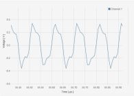
Triangle wave - 10 MHz: looks even better than the 1 MHz waveform. Same picture is displayed on my PM scope, however the amount of measurement points per period (~12) is far too low.
Summary: at higher frequencies the triangle- and especially the square waveforms look very much distorted. Strange, I assume the board was well tested against specs.
The visualisatioin at "higher" frequencies is not convincing, there are not enough measurement points available/displayed. I might be that the PC is not getting enough information, due to a 100Mbit hub in my LAN network. I assume that with better connection the result on the PC and on my PM33 50 will look more similar.
I don't believe that problems are coming from my measurement setup. My own SigGen made very decent 2MHz square waves. It might be due to HW/SW problems on my board, or some settings I am not aware of. In worst case the board is not performing as specified, but this I can hardly believe. Let's see what kind of advices the Red Pitaya forum may have.
I will search the web for additional tests, especially with square and triangle waveforms. Keep you posted...


